latex - Circuit diagrams in Latex | Circuit diagrams in Latex using Circuitikz - latex tutorial
Explain Circuit diagrams in Latex
- While Tikz provides several features and packages to generate diagrams and all sorts of other drawings, it unfortunately lacks a good package to layout electric circuits.
- Using the package circuitikz we can simply solve this problem.
- It extends provides a new environment circuitikz in which we can easily draw our circuits in no time.
Sample Code:
\documentclass{article}
\usepackage{tikz}
\usepackage{circuitikz}
\begin{document}
\begin{figure}[h!]
\begin{center}
\begin{circuitikz}
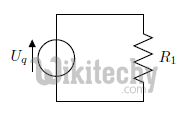
\draw (0,0)
to[V,v=$U_q$] (0,2) % The voltage source
to[short] (2,2)
to[R=$R_1$] (2,0) % The resistor
to[short] (0,0);
\end{circuitikz}
\caption{My first circuit.}
\end{center}
\end{figure}
\end{document}
Output:
The above code will create the following circuit diagram in our document:
- The circuit will be drawn in the same way as a path in tikz, but we specify special options for the elements:
\draw (0,0)
      to[V,v=$U_q$] (0,2) % The voltage source
- Starting at (0,0) we will draw a voltage source specifying the [V,v=$U_q$] options to the coordinates (0,2), where V chooses the symbol for a voltage source and the v=$U_q$ draws the voltage arrow next to it. Then we proceed to the resistor:
to[short] (2,2)
      to[R=$R_1$] (2,0) % The resistor
- We first must draw a short circuit from (0,2) to (2,2) and then put the resistor symbol on the path from (2,2) to (2,0) note that this time the label of the element must be specified directly (R=$R_1$).
- A list of all available elements for circuits is available in the circuitikz manual.
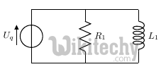
- we want to add an inductor parallel to the Resistor.
- The easiest way is to add a new draw command like this:
Sample Code:
\begin{circuitikz}
      \draw (0,0)
      to[V,v=$U_q$] (0,2) % The voltage source
      to[short] (2,2)
      to[R=$R_1$] (2,0) % The resistor
      to[short] (0,0);
      \draw (2,2)
      to[short] (4,2)
      to[L=$L_1$] (4,0)
      to[short] (2,0);
   \end{circuitikz}
Output:
After compilation we'd get the following circuit diagram:
Sample Code:
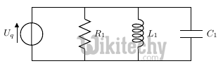
Adding a capacitor next to it, is just as simple:
\begin{circuitikz}
      \draw (0,0)
      to[V,v=$U_q$] (0,2) % The voltage source
      to[short] (2,2)
      to[R=$R_1$] (2,0) % The resistor
      to[short] (0,0);
      \draw (2,2)
      to[short] (4,2)
      to[L=$L_1$] (4,0)
      to[short] (2,0);
      \draw (4,2)
      to[short] (6,2)
      to[C=$C_1$] (6,0)
      to[short] (4,0);
   \end{circuitikz}
Output:
This would give us the following diagram:
- The circuitikz manual provides examples of all symbols and functions and can also be used for further reference.