8051 Microcontroller | 8051 Microcontroller Architecture
8051 Microcontroller Architecture
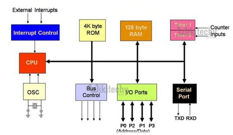
8051 Microcontroller Architecture
8051 Microcontroller
Instruction Register
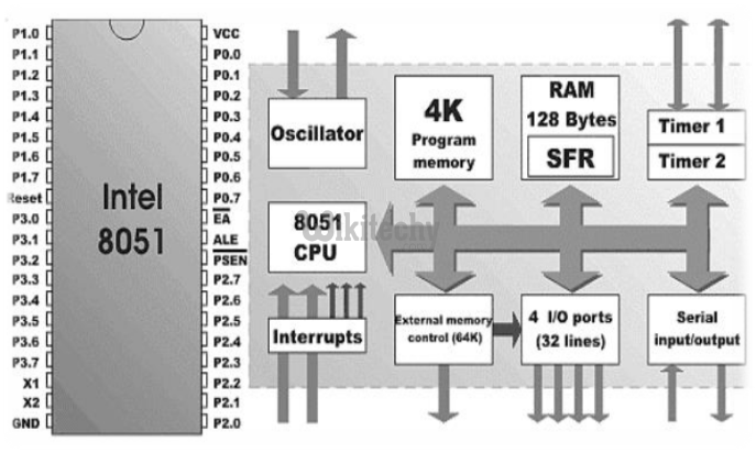
Microcontroller
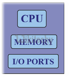
8-bit Microcontroller
- 8-bit CPU
- On-chip Oscillator
- 4KB of ROM (Program Memory)
- 128 bytes of RAM (Data Memory)
- 21 Special function register
- 32 I/O lines(Ports P0 to P3)
- 64 KB address space for external data memory - Data
- 64 KB address space for program memory - Code
- 2 - 16 bit timer/counter
- 5 source interrupt structure
- 5 duplex serial port
- Bit addressability
- Powerful bit processing capability
8-bit Microcontroller
SFR – Special Function Register
Special Function Register
128 Bytes RAM
- 64 KB address space for external data memory - Data
- 64 KB address space for program memory - Code
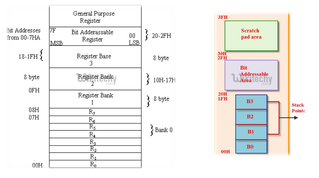
Bit Address Area
Data Bus
128 Bytes RAM / 4 KB ROM
128 Bytes RAM / 4 KB ROM
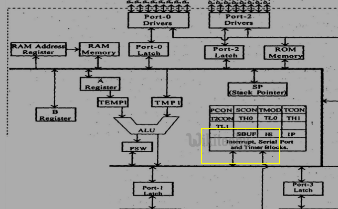
8051 Microcontroller Architecture
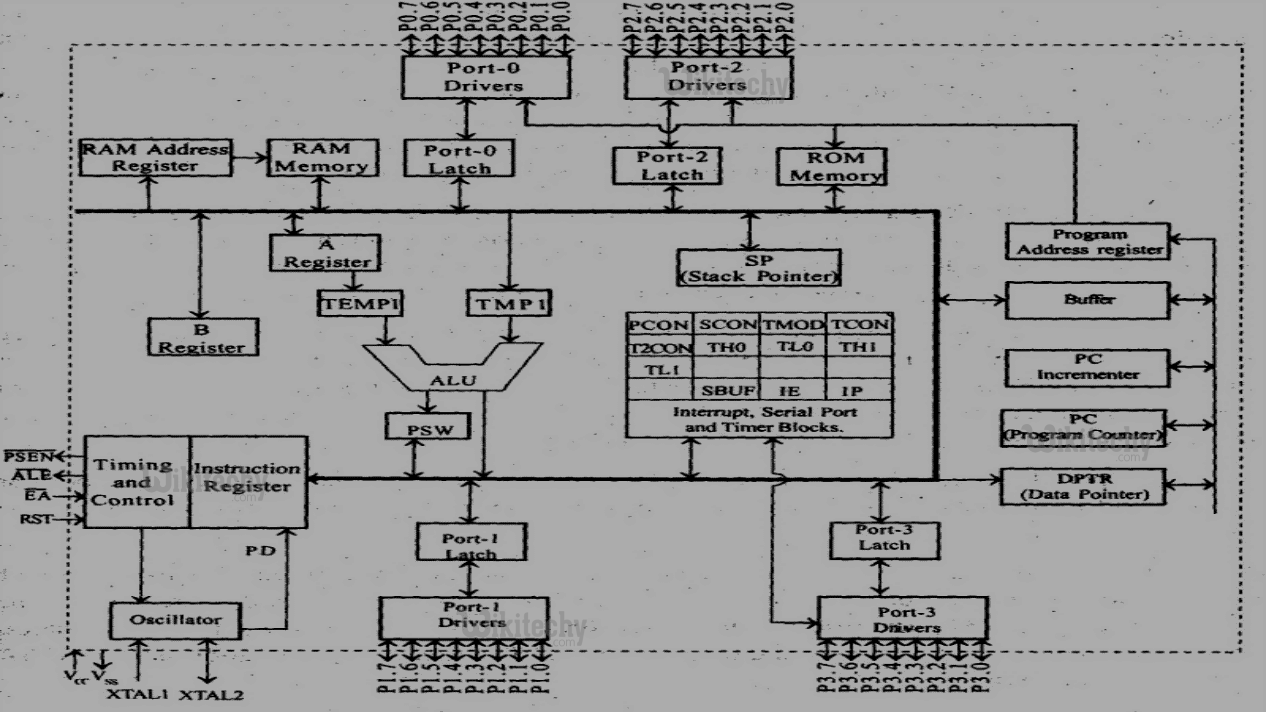
8051 Microcontroller
Ports in 8051 (P0,P1,P2 and P3)
Ports (0-3): There are 4 bidirectional input/ output ports of 8 bits each.
- P0 and P2 can be used as I/O ports or address lines for external memory
- P1 can be used as I/O ports
- P3 can be used as I/O ports and other alternate functions
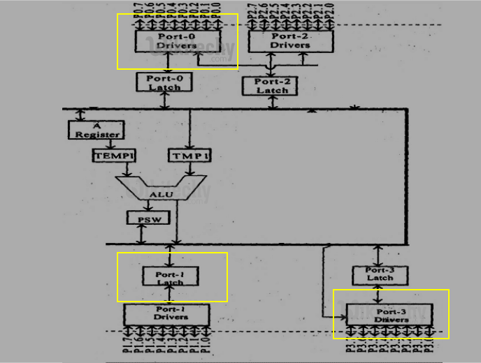
Ports in 8051 (P0,P1,P2 and P3)
Ports in Realworld
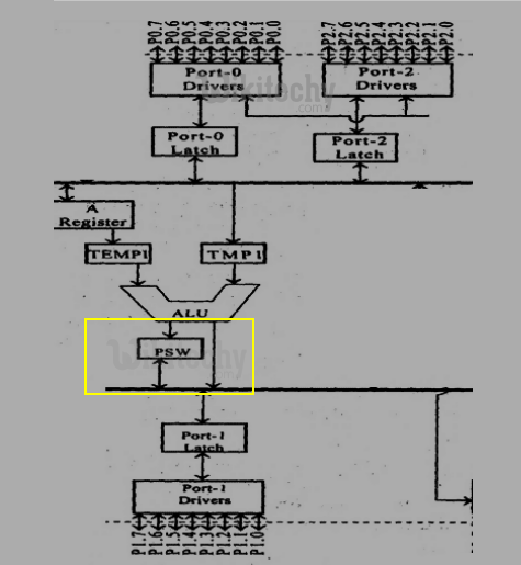
Program Status Word register (PSW)
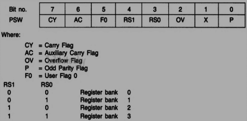
Program Status Word register in 8051 Microcontroller
PSW register in Real World
General-purpose flag (F0)
- This is a user-programmable flag; the user can program and store any bit of their choice in this flag, using the bit address.
Parity bit (P)
- It is set to 1 if the accumulator contains an odd number of 1s, after an arithmetic or logical operation.
Overflow flag (OV)
- This flag is set during ALU operations, to indicate overflow in the result. It is set to 1 if there is a carry out of either the D7 bit or the D6 bit of the accumulator.
Auxiliary carry flag (AC)
- This flag is set when there is a carry out of the D3 bit of the accumulator.
Carry flag (CY)
- This flag is used to indicate the carry generated after arithmetic operations.
Register bank Select Bits (RS0 & RS1)
- These bits are user-programmable. The register bank can be selected by using RS0 and RS1bits.
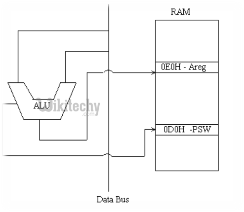
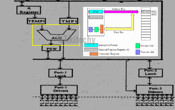
Arithmetic and Logic Unit (ALU)
- Arithmetic and Logic Unit performs 8 bit arithmetic and logical operations over the operands held by the temporary registers TMP1 and TMP2.
- Users cannot access temporary registers.
Arithmetic Logic Unit in 8051 Microcontroller
Address Bus
ACC Register
- ACC is an 8 bit register called as A register.
- It is used to hold one of the operands during ALU operation and the result is stored in the ACC.
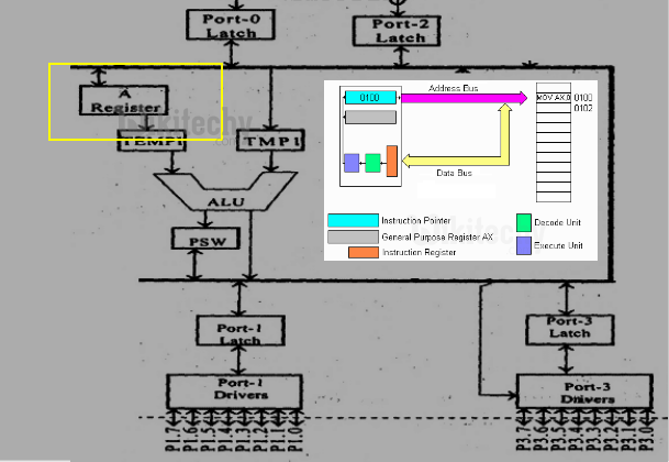
ACC Register in 8051 Microcontroller
Special Function Register in 8051 Microcontroller
Special Function Register in 8051 Microcontroller
B register
- It is an 8 bit register. This register is used to hold one of the operands for multiply and divide operation and a part of the result is stored in the register.
- It also acts like a scratch pad or temporary register
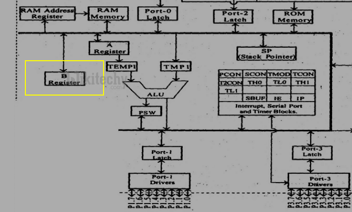
B Register in in 8051 Microcontroller

B Reg in Realworld
Stack Pointer
- It is an 8 bit register. This pointer can point any location in the internal data RAM from 0 - 127.
- When reset, this register is initialized into 07H.
- During PUSH and CALL instruction the stack pointer is first incremented and then data is stored in the stack.
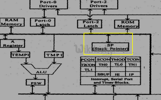
Stack Pointer in in 8051 Microcontroller
Push Operaions in Stack
Pop Operations in stack
Serial Data buffer(SBUF)
- The serial port data buffer internally consists of two independent register such as transmit buffer and receive buffer at the same location.
- The transmit buffer is parallel in serial out register.
- The serial data receive buffer is a serial in parallel out register. The serial data buffer is identified as SBUF.
Serial Data buffer(SBUF) in 8051 Microcontroller

Serial Data buffer(SBUF) Register in Realworld
Timers registers
- Two 16 bit registers can be accessed as their lower and upper bytes.
- TL0 and TH0 represent the lower byte and higher byte of the timing register 0.
- TL1 and TH1 represents the lower byte and higher byte of the timing register 1.
Timer Register in 8051 Microcontroller
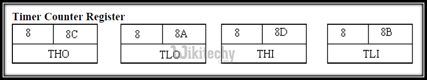
Timer Counter Register
Timer Register in RealWorld
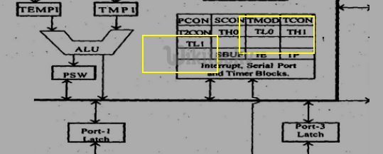
Control Registers
- Special function registers IP, IE, TMOD, TCON, SCON and PCON contain control and status information for interrupts, timers/ counters and serial port.
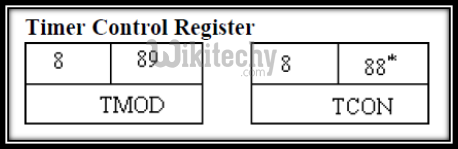
Timer Control Registers in 8051 Microcontroller
Timer Control Registers in Realworld
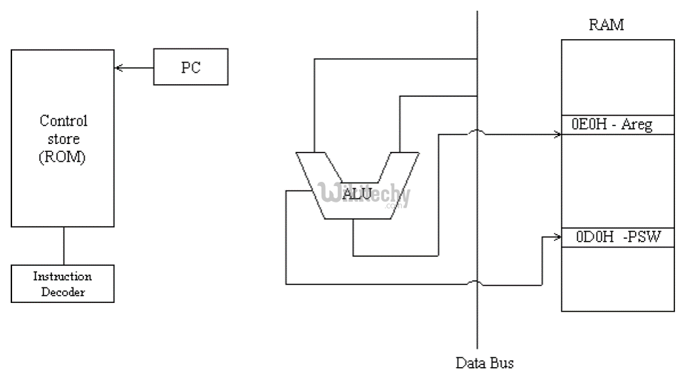
Instruction register
- This register decodes the opcode of an instruction to be executed and gives the information to the timing and control unit to generate necessary signals for the execution of an instruction.
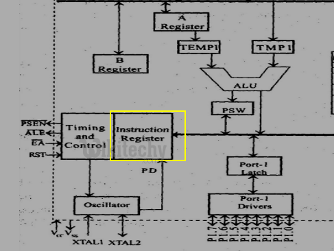
Instruction register in 8051 Microcontroller
Instruction register in Realworld
8051 Clock and Instruction Cycle
- In 8051, one instruction cycle consists of twelve (12) clock cycles. Instruction cycle is sometimes called as Machine cycle.
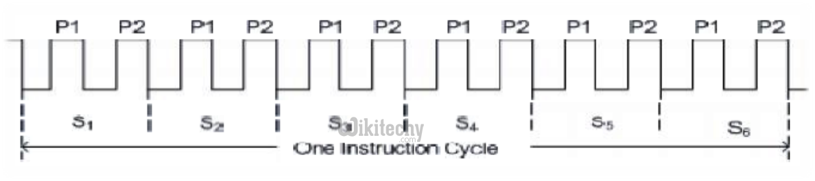
Instruction Cycle
- In 8051, each instruction cycle has six states (S1 – S6).
- Each state has two pulses (P1 and P2).
Timing and control unit
- This unit derives all the necessary timing and control signals required for the internal operation of the circuit.
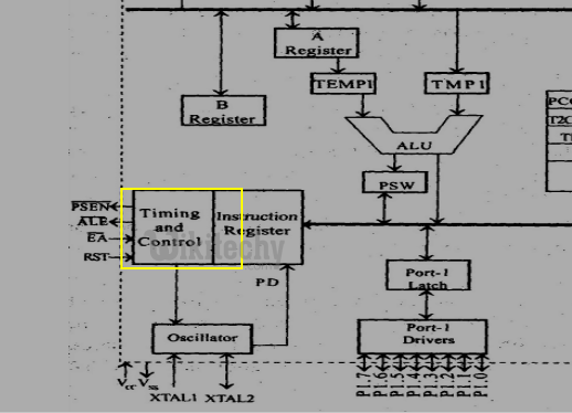
Timing and Control unit in 8051 Microcontroller
Oscillator
- This circuit generates the basic timing clock signal for the operation of the circuit using crystal oscillator.
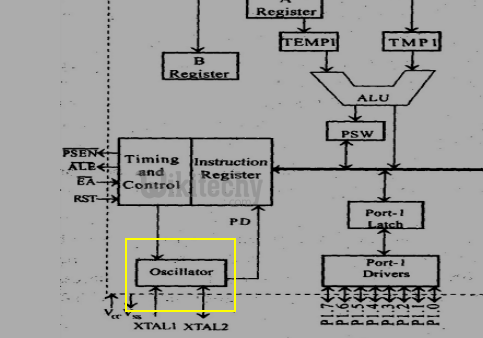
Oscillator in 8051 Microcontroller

Oscillator in RealWorld
Program Counter
- It is a 16 bit register. It points to the address of next instruction to be executed from ROM and access from 0000 to FFFF.
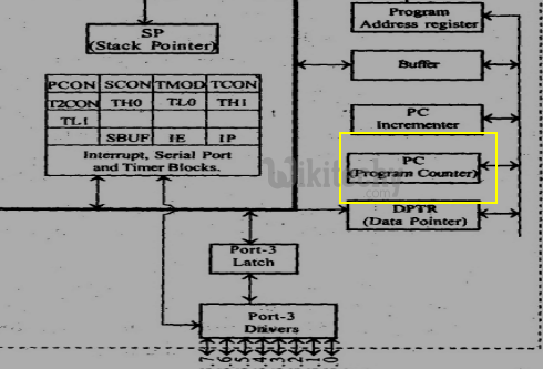
Program Counter in 8051 Microcontroller
Program Counter in Realworld