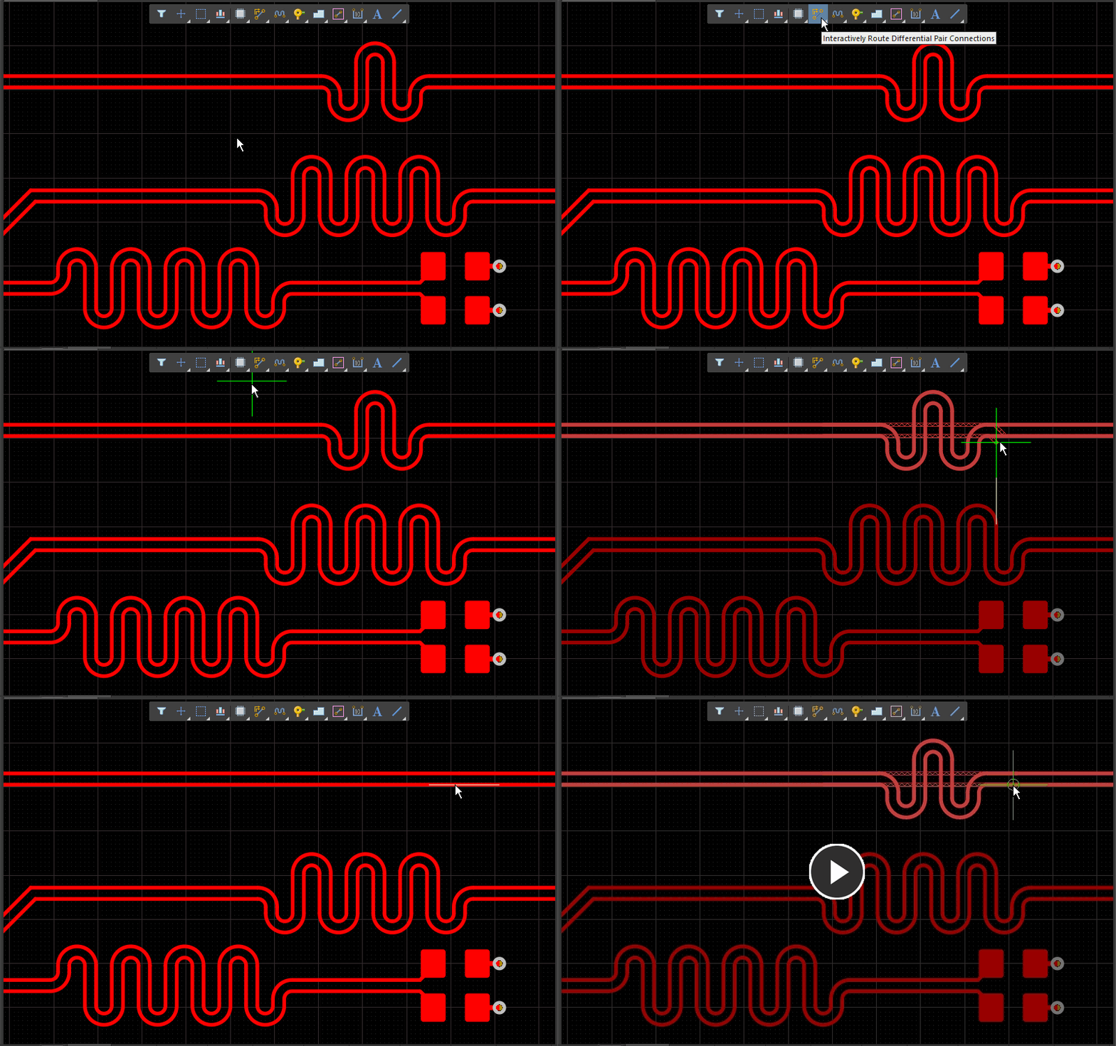
Differential routing is a common routing technique, effective in decreasing EMI or electromagnetic interference on a printed circuit board (PCB). The interference caused has the potential to make sensitive signals ineffective or weaker, which would, in turn, make the whole design imperfect and inefficient.
By inducing a decreased current flow via the ground plane, differential routing is highly effective in countering common noise issues that can interfere with sensitive signals. Unfortunately, it’s not a particularly simple technique, and it brings with it its own set of issues.
This article will highlight a few of those issues, along with some general guidelines to make your differential routing processes a little less troublesome.
Trace Length Matching
The two traces carrying positive and negative signals must be of the same length in order for the opposing signals to arrive at the same exact time. There are margins for error here fortunately, but they are not very lenient.
While routing a high-speed signal, even a small trickle of current into the ground plane will cause a disturbing amount of electromagnetic interference, thus defeating the purpose of the differential routing method. Use meanders and segment the trace to facilitate this necessary process of matching lengths, if and when required.
Matching Impedance
Impedance occurs when the two differential pairs are routed very close to each other on the PCB, but the current crosstalk will continue to cancel each other out, as long as the distance in between each of the two are equal at all points. If the distance begins to increase at some point, the differential impedance will also increase with it proportionately.
The same effect is also seen while changing layers through the vias, as well as in a number of other scenarios. In order to counter the differential impedance, you will need an impedance calculator that can set the impedance controlled widths for the differential routing automatically. It eliminates trial and error from the equation altogether, adding to productivity and time-efficiency.
Separation Distance Control
Controlling the separation distance between the traces is effective for the reasons stated above, but it also has an additional advantage. Differential routing is, by default, a routing method that requires more space, so by keeping the separation distance to a minimum, you can reduce both the differential impedance and physical space requirements on the PCB.
Additionally, the inevitable current loop created from the crosstalk that we discussed in the previous point will also be small, thus reducing the chances of seeing EMI interference from a differential pair.
Proximity of the positive and negative trace routes will be particularly necessary, when the traces host high-speed signals, because if the distance between the two is large enough, the consequent current loop and the ensuing EMI will be too high to work with.
There is no doubt about the fact that differential pairing is complicated and takes a lot of time and meticulous work. At the same time, due to the routing method’s unmatched ability to protect weaker signals against common noise interference, the effort is well worth it.
